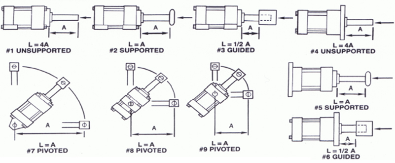
Figure 7.
Stop tubes are used to reduce the bearing load encountered in long stroke cylinders when the piston rod is extended.
By separating the piston and rod bearing with a stop tube, the life of the bearing cartridge will be increased and the tendency of the rod to buckle will be reduced.
To determine the length of stop tube required, locate the application in the drawings above and calculate “L” from the cylinder “A” dimension with the piston rod extended. For an “L” longer than 40″: one inch of stop is required for every 10″ over 40″ plus one inch for any remainder.
EXAMPLE: An MP1 Rear Clevis Mount Cylinder with Rod Eye, 4″ Bore, 34″ Stroke, 2″ Rod is operating at 500 PSI.
This application matches Fig. 7 (above) and L = A.
L = XC dim. + 2 x stroke + Rod Eye CA dim..
L = 7.5 + [2 x 34] + 3.44= 78.94″
78.94” – 40 = 38.94 = [3 x 10] + 8.94
Therefore a 4″ stop tube is required.
The required length of stop tube should be added to the cylinder stroke when ordering.
The above cylinder example would be ordered as 38″ Gross Stroke.
34″ Working Stroke with 4″ Stop Tube.
This is usually written 38″ [34″]w/4″ Stop Tube.
Rod Strength & Support (Column Strength)
To select the optimum rod diameter required for PUSH STROKE cylinders:
1. Determine the push stroke thrust using the cylinder forces chart on page 3.
2. Calculate the “L” value as for a stop tube and add stop tube length to given Working Stroke to obtain the Gross Stroke.
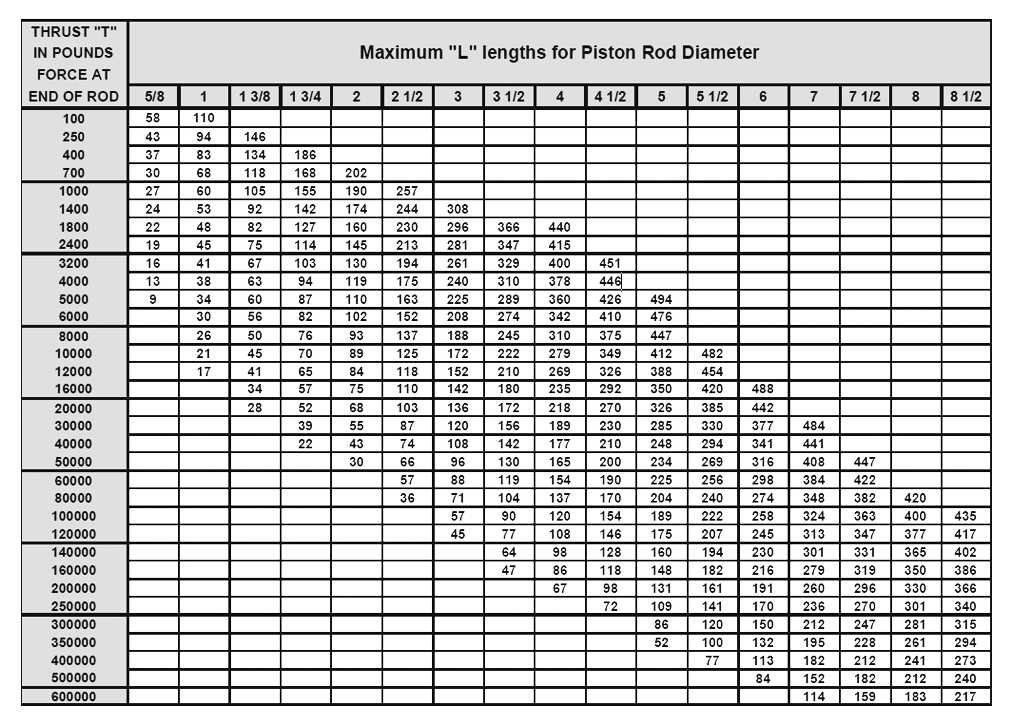
3. Locate the push stroke thrust in the left-hand column of the table below. If the exact thrust is not shown, use the next higher value.
4. Locate the calculated “L” length in the row across from the thrust value selected. If the exact “L” length is not shown, use the next longer value.
5. Find the minimum rod diameter for the application at the top of the column in which the “L” value is located.
Using the same cylinder as in the stop tube example, where “L” = 82.94″ including 4″ stop tube.
1. Find 6285 Ibs. force or the next higher value in first column. Use 8000 Ibs. as the nearest higher value.
2. Move across the row to 92, the next higher entry to 82.94. At the top of the column is found the optimum rod diameter for the application. A 2″ dia. piston rod is required.
By changing the cylinder mounting to a MT1 Head Trunnion which reduces the “L” dimension, a standard 1 3/8″ piston rod may be used.






Connect with Us